6. Periodic Maintenance
6.1. Maintenance Instructions
Before conducting any maintenance or troubleshooting activities, please carefully read this chapter, this manual, and related manuals to fully understand the safe maintenance and troubleshooting procedures.
Only personnel who have passed safety and other relevant training and have been authorized may perform maintenance on the robot system. Other relevant training includes robot system training and maintenance training conducted by the manufacturer, distributor, or local importer.
Operators should participate in safety training according to the regulations of each country.
Note

Name:Precautions for Using Robot Components
Only approved parts are allowed to be used.
If unauthorized parts are used without approval, the company shall not bear any responsibility. The company shall not be liable for any damage to the robot, accessories, or any other equipment caused by the use of unauthorized parts.
Note
名称:Robot Maintenance Precautions
Strictly perform maintenance according to the description in this manual. Do not disassemble or alter any parts not described in this manual without authorization. Incorrect disassembly, alteration of parts, or improper maintenance may cause abnormal operation of the robot system and create serious safety issues.
When an emergency situation requires entering the robot work area, the system should be stopped.
Please carry out maintenance and repair activities in the designated maintenance area. Before performing any maintenance, ensure that the robot is removed from the system and the robot power is turned off, to prevent the robot from suddenly moving due to system commands. It may receive system commands and move suddenly.
6.2. Periodic Maintenance
Table 6-1 Periodic Maintenance
component. |
Maintenance Mode |
Maintenance Cycle |
Shell |
Check for cracks,check the installation。 |
Once a month, replace as needed. |
drive wheel |
Check the wear condition of surface texture. |
Once a month, replace as needed. |
Universal wheel |
Check the surface texture for wear, check whether the wheels are tangled with debris. |
Once a month, replace as needed. |
laser |
Check the surface for scratches, cracks. |
once a week,replace as needed。 |
Emergency Stop Button |
Check whether it can be pressed down normally and rotate with rebound. |
Once every three months, replace as needed. |
Safety label |
Check whether it is worn or clearly visible. |
Once every six months,replace as needed。 |
6.2.1. Replace battery
Note
Name: Battery Replacement Precautions
Replace batteries in the area designated for AMR battery charging and swapping, and keep away from open flames、 high temperatures、 humidity and crowded workplaces, and do not set up maintenance sites for disassembly、 welding and other repairs of vehicles or batteries in this area。
When the robot battery is damaged or reaches its specified service life, it can be replaced by following the steps below:
Power off the robot. Use the key to open and pull open the battery compartment door, and manually disconnect the three connectors shown in the figure before removing the battery.
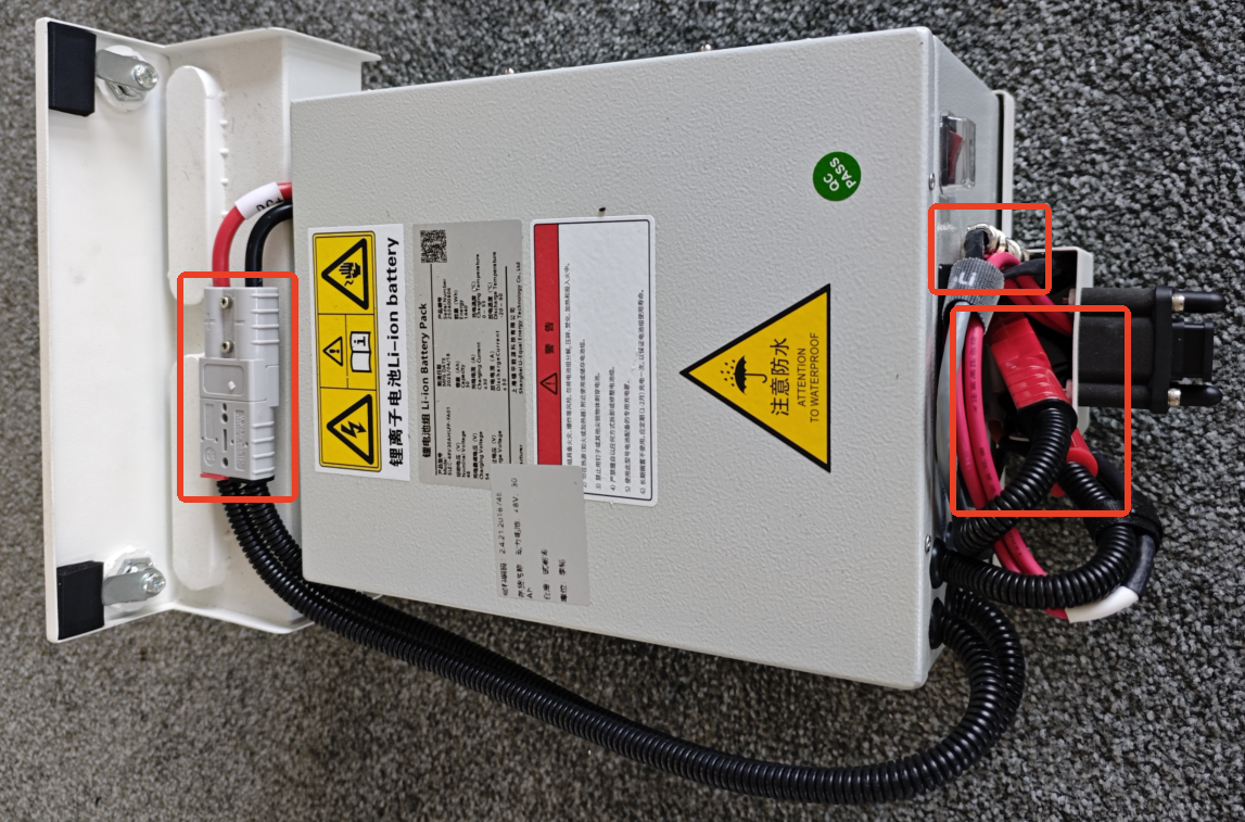
Diagram 6-2 Replace Battery
Replace with a new battery,close the compartment door,turn the key to secure it,ensure the compartment door is closed,replacement complete。The left side is closed,the right side is open。
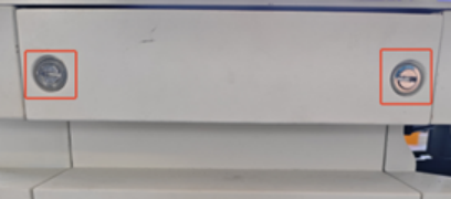
Keyhole closed state
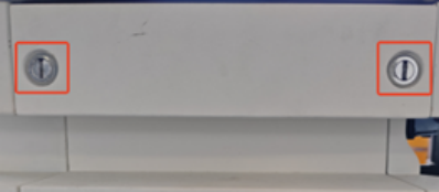
Keyhole open state
Chart 6-3 Battery Drawer Switch Status
6.3. clean
Floor cleaning requirements:
Check the ground conditions daily, and promptly clean dust, foreign objects, and liquid contamination to prevent the robot from slipping.
Promptly clean the traces left by the universal wheels on the ground, avoid producing heavy traces。
6.3.1. Laser cleaning
Note

Name:Laser Cleaning Precautions。
Improper cleaning or failure to clean the laser may cause the following problems:
The robot cannot detect the marked / pallet rack.
The robot entered an emergency stop state without a clear reason.
Please clean the laser according to the following instructions,otherwise it may cause damage to the laser lens or malfunction:
Keep the laser glass surface clean and regularly remove dust.
Never dry-wipe the laser glass surface. Use a damp soft cloth to clean, adding a little detergent if necessary.
Never use corrosive solvent-based cleaners such as acetone.
6.4. Store
6.4.1. Robot storage
Robots that are out of service for a long time should take anti-corrosion measures when stored, disconnect the battery from AMR, and ensure the battery is recharged once a month.
Battery storage
Battery packs should be stored under the conditions of ambient temperature 0-40℃ and relative humidity 10%-90%RH.
The battery pack should avoid contact with corrosive substances or magnetic environments.
Battery packs should be stored in a clean, dry, and well-ventilated environment, away from fire sources or heat sources.
When the battery pack is stored for a long time without use, charge and discharge the battery pack once a month.
6.4.2. Charger Storage
When the charger is not in use, it should be placed in the packaging box.
The extreme temperature in the warehouse should be -20~70℃,the normal temperature should be -20~50℃,the relative humidity is 5~90%,and there must be no harmful gases,flammable items,explosives,corrosive and other chemical items and strong mechanical vibration、impact and magnetic field influence inside the warehouse.
The packaging box must be placed at least 20cm above the ground,and 50cm away from walls,heat sources,and ventilation openings。The charger can be stored under such storage conditions for two years,and after more than two years it must be re-tested.
The charger must be powered on once every three months, and the power-on duration should be no less than 0.5 hours.
6.5. Packaging and Transportation
When transporting the robot, please use the original packaging materials.
Original packaging includes:
Packaging box body
Packaging cover plate(slope)
Slope assist wooden board
Packaging side panel
Pearl foam protective block
Packaging robot steps:
Shut down the robot.
Execute the unpacking steps in reverse order
Battery transportation
Battery transport must comply with relevant regulations, and the specific requirements vary slightly depending on the mode of transport (land, sea, or air).
Ensure compliance with the safety precautions and guidelines in this chapter to transport batteries.
The battery should be packed in boxes for transportation. During transportation, it should be protected from violent vibration, impact, or extrusion, and from exposure to sunlight and rain.
6.6. Typical Fault Analysis and Handling
6.6.1. Safety Warning
Warning
High voltage danger! The battery pack contains high voltage direct current, non-professionals are prohibited from disassembling.
Short circuit risk! When operating, use insulated tools to prevent short circuit between positive and negative terminals.
Burn risk! There may be high temperature and electrolyte leakage risks when the battery fails. Insulating gloves and safety goggles must be worn during operation.
Disconnect power first,then operate! Before performing any inspection or connection/disconnection operation,please make sure AMR is completely powered off,and disconnect the battery pack’s main power switch or connector。
6.6.2. Fault diagnosis process
When AMR experiences a power-related fault, please follow the following general procedure:
Observe the phenomenon: Confirm the specific manifestations of AMR (e.g., failure to power on, sudden shutdown, inaccurate battery display, failure to charge, etc.).
Check alarm:ViewAMRthe battery fault alarm code on the HMI upper computer system.
Preliminary troubleshooting: Conduct basic physical inspections (such as: whether the wiring is loose, whether the charging contacts are clean, whether the fuse is functioning properly).
Recording and Reporting:Record fault codes, handling processes, and results in detail. For recurring or unresolvable faults, report them promptly to supplier technical personnel for coordinated troubleshooting.
6.6.3. AMRTypical Fault Analysis of Drive System
Table 6-2 AMR Drive System Typical Fault Comparison Table
Fault code/Phenomenon |
possible cause |
Troubleshooting steps |
Solutions and Preventive Measures |
code: 0002 (example:encoderABZ/not connected) |
The drive cannot receive the encoder feedback signal from the motor. |
|
Re-plug the encoder connector and check whether the pins are bent. |
code: 0002 (example:encoderABZ/not connected) |
The drive cannot receive the encoder feedback signal from the motor. |
|
At the encoder connector, measure whether the supply pin voltage is normal. |
code: 0002 (example:encoderABZ/not connected) |
The drive cannot receive the encoder feedback signal from the motor. |
|
Use the multimeter’s continuity mode to check whether each core wire of the encoder cable is conductive. |
code: 0002 (example:encoderABZ/not connected) |
The drive cannot receive the encoder feedback signal from the motor. |
|
|
code : 0004 ( encoder UVW/ encoder interior ) |
Motor power circuit abnormal |
|
Strictly connect according to the corresponding relationship between the drive terminal (U/V/W) and the motor junction box (U/V/W). |
code : 0004 ( encoder UVW/ encoder interior ) |
Motor power circuit abnormal |
|
When power is off, use a multimeter in resistance mode to measure the resistance between the output terminals of the driver UVW, and respectively to PE (ground). |
code : 0004 ( encoder UVW/ encoder interior ) |
Motor power circuit abnormal |
|
|
code : 0004 ( encoder UVW/ encoder interior ) |
Motor power circuit abnormal |
|
|
Code : 0020( Example:Overvoltage ) |
Bus voltage exceeds safety threshold. |
Excessive regenerative energy: Motor decelerates too abruptly (emergency stop, rapid downhill), kinetic energy converts to electrical energy and feeds back to the drive. |
Confirm that the braking resistor is correctly connected; use a multimeter to measure whether the resistance value is normal, and check for any signs of burning. |
Code : 0020( Example:Overvoltage ) |
Bus voltage exceeds safety threshold. |
Power supply voltage abnormality: the external supply voltage itself is too high or unstable. |
Based on motor inertia and load, recalculate and replace the braking resistor with appropriate power and resistance. |
Code : 0020( Example:Overvoltage ) |
Bus voltage exceeds safety threshold. |
Fault in the internal capacitor or voltage detection circuit of the driver. |
Check power supply: Use a multimeter to measure the voltage at the driver input terminals. |
Code: 0040 (Example:Low voltage) |
Bus voltage falls below the normal operating threshold. |
Main power issue: AMRbattery power depleted or aged. |
Tighten all power terminal blocks and check whether the relay contacts are in good condition. |
Code: 0040 (Example:Low voltage) |
Bus voltage falls below the normal operating threshold. |
Power supply module or detection circuit fault. |
Disconnect the motor from the load (such as a reducer, wheels), and run the motor unloaded. |
code: 0080 (example:overcurrent) |
The output current far exceeds the rated value of the drive or motor. |
The motor shaft was stuck by the mechanical structure,causing the current to rise sharply。 |
Check whether the wiring sequence of UVW is correct. |
code: 0080 (example:overcurrent) |
The output current far exceeds the rated value of the drive or motor. |
Phase-to-phase short circuit: UVW insulation damage between each pair. |
|
code: 0080 (example:overcurrent) |
The output current far exceeds the rated value of the drive or motor. |
Wiring error or poor contact. |
6.6.4. AMRBattery system fault code
Table 6-3 AMR Battery System Typical Fault Comparison Table
fault code |
Description |
protection type |
1001 |
Low battery warning |
Battery-related errors |
1002 |
Charging fault |
Battery-related errors |
1003 |
Battery temperature abnormal |
Battery-related errors |
1100 |
Overvoltage Protection |
Voltage protection |
1101 |
Undervoltage protection |
Voltage protection |
1102 |
Discharge overcurrent protection |
Current protection |
1103 |
Charging overcurrent protection |
Current protection |
1104 |
short circuit protection |
Current protection |
1105 |
MOS tube high-temperature protection |
Temperature protection |
1106 |
Low-temperature charging protection |
Temperature protection |
1106 |
Low-temperature charging protection |
Temperature protection |
1107 |
High Temperature Charging Protection |
Temperature protection |
1108 |
Discharge low temperature protection |
Temperature protection |
1109 |
Discharge high-temperature protection |
Temperature protection |
6.6.5. AMRDrive system alarm code
Table 6-4 servo drive fault code table
fault code |
fault name |
processing method |
1 |
Software overcurrent fault |
1、check whether joint load or resistance has become larger or abnormal
2、If the fault still cannot be eliminated, repair or replace the driver board
|
2 |
Overvoltage fault |
Reduce robot operating speed or acceleration |
3 |
Undervoltage fault |
1、check whether the power voltage output of the control box 48V is abnormal
2、Check whether the driver board and joint housing are short-circuited
3、If the fault is still not eliminated, repair or replace the drive board
|
4 |
Overheating Fault |
Reduce robot load or lower robot operating speed |
5 |
overload fault |
Reduce robot load or lower robot operating speed |
6 |
Overspeed Fault |
1、check whether the magnetic encoder assembly and the motor shaft fixing set screw are loose
2、re-perform encoder zero calibration
3、If the fault is still not resolved, repair or replace the magnetic encoder component.
|
7 |
Abnormal parameter fault |
Repair or replace the drive board |
8 |
Flying Car Malfunction |
1、check whether the magnetic encoder assembly and the motor shaft fixing set screw are loose
2、re-perform encoder zero calibration
3、If the fault is still not resolved, repair or replace the magnetic encoder component.
|
9 |
Position error fault |
1、check whether joint load or resistance has become larger or abnormal
2、If the fault still cannot be eliminated, repair or replace the driver board
|
10 |
Position overflow fault |
1、Check whether the hard limit is loose
2、Re-perform robot zero calibration
|
11 |
Hardware overcurrent fault |
Repair or replace the drive board |
12 |
Drive inhibit fault |
Not enabled |
13 |
Motor locked-rotor fault |
1、check whether the brake electromagnet is engaged
2、Check whether it hits the hard limit
3、If the fault is still not eliminated, repair or replace the drive board
|
14 |
Power supply fault |
Not enabled |
15 |
STO fault |
Not enabled |
16 |
Phase current AD zero adjustment fault |
Repair or replace the drive board |
17 |
EEPROM Fault |
Repair or replace the drive board |
18 |
Hall fault |
1、Check whether the Hall wiring harness is securely connected, and whether there is any short circuit or open circuit.
2、if the fault is still not eliminated, repair or replace the joint.
|
19 |
Encoder fault |
Repair or replace the magnetic encoder assembly |
20 |
Encoder zeroing fault |
1、re-perform encoder zero calibration
2、If the fault is still not eliminated,repair or replace the magnetic encoder assembly
|
21 |
EncoderZphase signal loss fault |
Not enabled |
22 |
Encoder count fault |
Not enabled |
23 |
Encoder multi-turn data overflow fault |
Not enabled |
24 |
External clock fault |
Repair or replace the drive board |
25 |
UVW phase sequence fault |
Not enabled |
26 |
FPGAfault |
Not enabled |
27 |
Return-to-zero fault |
Not enabled |
28 |
Magnetic encoder fault |
1、check whether the magnetic encoder assembly and the motor shaft fixing set screw are loose
2、If the fault is still not eliminated,repair or replace the magnetic encoder assembly
|
29 |
Motor power line disconnection fault |
1、check whether the motor power cable is securely plugged in, and whether there is any short circuit or open circuit
2、If the fault still cannot be eliminated, repair or replace the driver board
|
30 |
EtherCATFault |
1、Check whether the network cable is securely plugged in, whether there is short circuit、open circuit
2、If the fault still cannot be eliminated, repair or replace the driver board
|
31 |
EtherCAT_SM_DOGfault |
1、Check whether the network cable is securely plugged in, whether there is short circuit、open circuit
2、If the fault still cannot be eliminated, repair or replace the driver board
|
32 |
EtherCAT_FATALSYNC fault |
1、Check whether the network cable is securely plugged in, whether there is short circuit、open circuit
2、If the fault still cannot be eliminated, repair or replace the driver board
|
33 |
EtherCAT_SYNCFault |
1、Check whether the network cable is securely plugged in, whether there is short circuit、open circuit
2、If the fault still cannot be eliminated, repair or replace the driver board
|
34 |
EtherCAT_RFTfault |
1、Check whether the network cable is securely plugged in, whether there is short circuit、open circuit
2、If the fault still cannot be eliminated, repair or replace the driver board
|
35 |
Drive axis address fault |
1、re-perform drive axis address configuration
2、If the fault still cannot be eliminated, repair or replace the driver board
|
36 |
Robot zero calibration fault |
1、Re-perform robot zero calibration
2、first use JLINK to erase FLASH, then re-download the program and perform zero calibration.
3、If the fault is still not eliminated, repair or replace the drive board
|
37 |
Encoder communication fault |
1、Check whether the encoder wiring harness is firmly plugged in, and whether there is any short circuit or open circuit.
2、If the fault is still not eliminated,repair or replace the magnetic encoder assembly
|
40 |
Magnetic encoder module fault-zero calibration fault |
1、re-perform zero calibration on the magnetic encoder assembly
2、If the fault is still not eliminated,repair or replace the magnetic encoder assembly
|
41 |
Magnetic encoder module fault-multi-turn fault |
1、check whether the magnetic encoder assembly and the motor shaft fixing set screw are loose
2、If the fault is still not eliminated,repair or replace the magnetic encoder assembly
|
42 |
Magnetic encoder module fault-multi-turn small magnetic encoder fault |
1、Check whether the multi-turn small magnetic encoder chip is abnormal
2、If the fault is still not eliminated,repair or replace the magnetic encoder assembly
|
43 |
Magnetic encoder module fault-multi-turn large magnetic encoder fault |
1、Check whether the multi-turn large magnetic encoder chip is abnormal
2、If the fault is still not eliminated,repair or replace the magnetic encoder assembly
|
44 |
Magnetic encoder module fault-single-turn magnetic encoder fault |
1、Check whether the single-turn magnetic encoder chip is abnormal
2、If the fault is still not eliminated,repair or replace the magnetic encoder assembly
|
45 |
Magnetic encoder module fault-Optical encoder fault |
1、check whether the optical encoder disk is contaminated or not firmly adhered
2、If the fault is still not eliminated,repair or replace the magnetic encoder assembly
|