3. Product Introduction
3.1. Introduction
AMR is a universal mobile robot chassis using laser SLAM. The product provides core map building and positioning navigation functions, and reserves rich I/O, EtherCat/net and other interfaces for expanding upper mechanisms, thereby helping users quickly implement various applications of mobile robots.
This product was developed and designed by Fairino(Suzhou)Robotics Technology Co., Ltd.。
Fairino (Suzhou) Robotics Technology Co., Ltd.©All rights reserved.
Some names in this document and possibly other names without registered trademark symbol ®,they are all registered trademarks of Fairino(Suzhou)Robotics Technology Co., Ltd.
3.2. Product Dimensions
3.2.1. Robot Dimensions
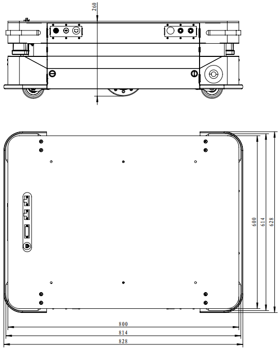
Chart 3-1 Robot dimensions
3.3. Main Label
3.3.1. Precautions
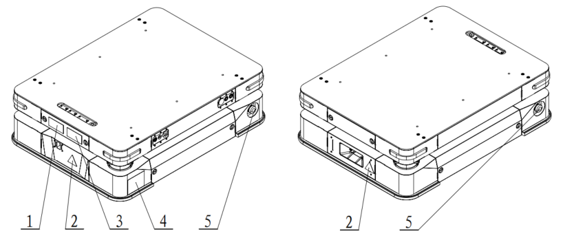
1-warning label1; 2-warning label2; 3-warning label3

Warning label1
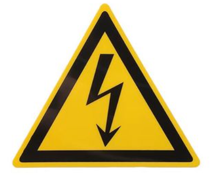
Warning label2
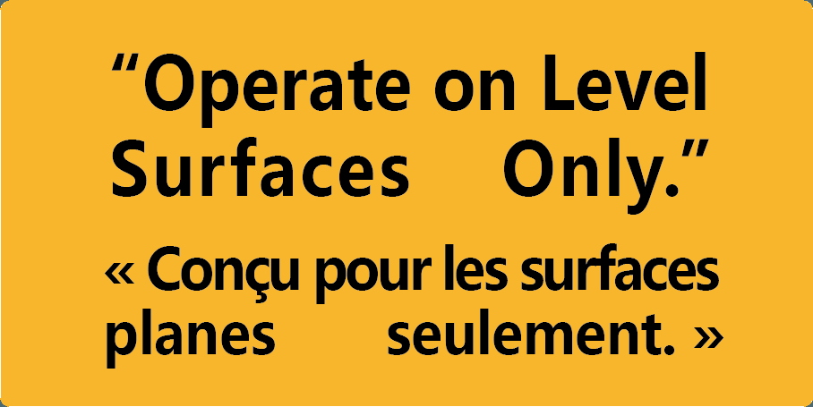
Warning label 3
Chart 3-2-1 Warning Labels and Their Locations
Warning label1: warning against carrying passengers;
Warning label2:Warning of electric shock;
Warning label3:warns that operation should only be performed on a horizontal surface.
3.3.2. nameplate
4-Nameplate
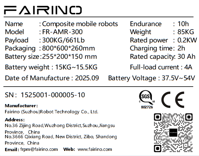
Figure 3-3 body nameplate
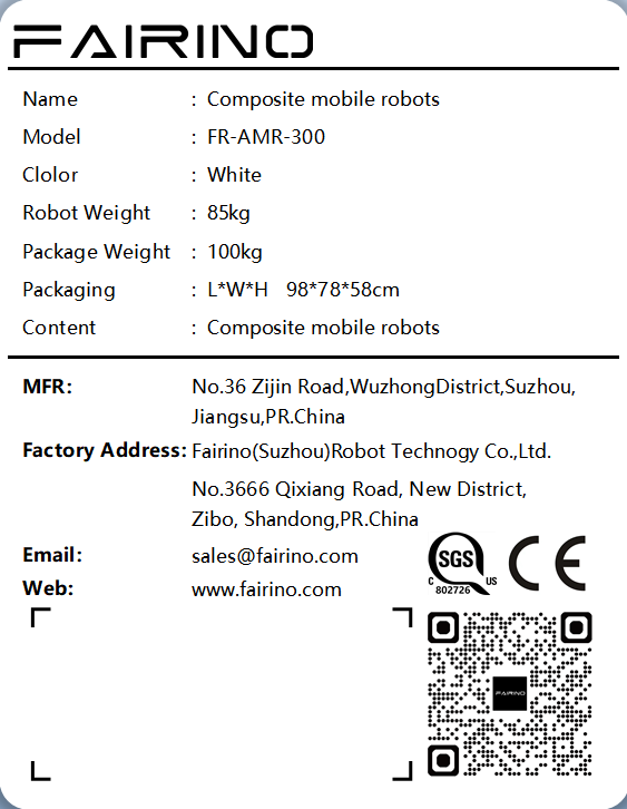
Diagram 3-4 packing box nameplate
3.4. Laser system
AMR Configure Oulei Laser 1B-S5 laser,the main functions are as follows:
Scan Map
Positioning and Navigation
Identify obstacles
3.4.1. Detection range
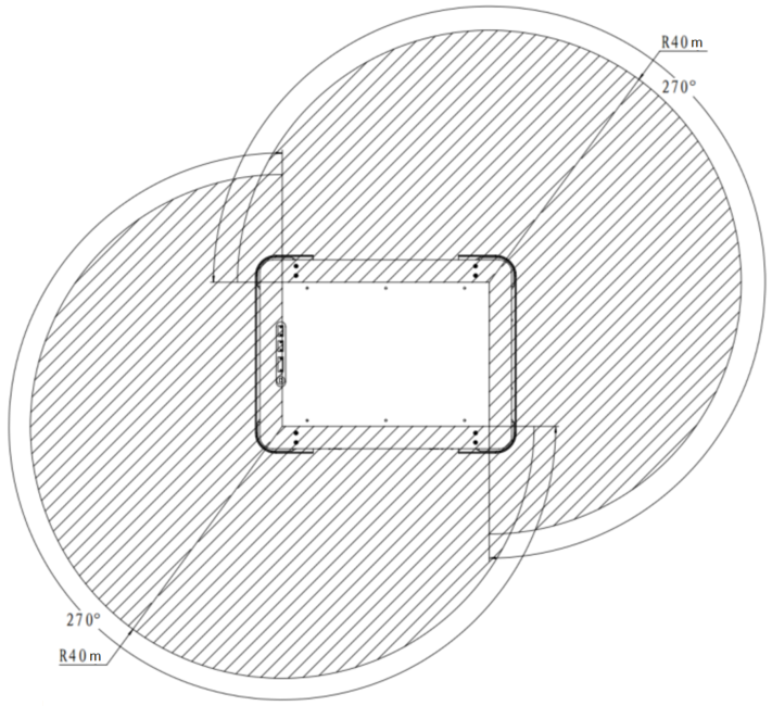
Chart 3-5 detection range
Table3-1 detection range
model |
definition |
parameter |
AMR-300 |
Detection distance |
40m |
AMR-300 |
detection angle |
270° |
3.4.2. Detection blind zone
Due to the characteristics of the laser sensor, objects below or above the laser detection height cannot be detected.
3.4.3. Action after detecting an obstacle
When the AMR leaves the factory, the default deceleration and stop zones for the test environment have already been set. After the map is built, deceleration and stopping upon obstacle detection can be achieved within the planned obstacle avoidance zones.
In the stop area, the laser detects an obstacle, and the robot stops.
OSSD The detection and obstacle avoidance range is:directly ahead of the driving path 1.5m*1.4m rectangular area.
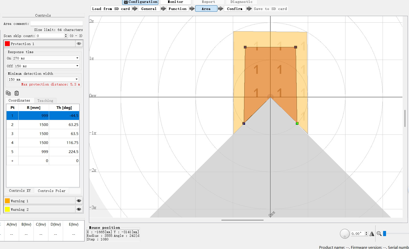
Chart 3-6-1 LiDAR obstacle avoidance range
3.4.4. Laser Characteristics and Usage Limitations
3.4.4.1. Effective distance
The effective distance of the OLEI Laser 1B-S5 laser during normal operation is 0.1m~25m, therefore when the laser is very close to an object or very far away, the laser data may not be accurate, therefore during use, the laser should not be placed particularly close to walls or other objects (at least 10cm space should be left).
3.4.4.2. Specular reflection object
Since laser measurement calculates distance based on the received reflected laser light,objects of different materials will have different effects on laser measurement,for natural object surfaces,as long as the diffuse reflection is uniform,the noise when the laser irradiates the surface is relatively small,and the measurement accuracy is relatively high。Objects with smooth surfaces,mainly those with specular reflection,have relatively large measurement noise,and measurement accuracy will decrease。Therefore,if the environment is full of specular reflective objects,the robot may not be able to construct an accurate environment map,and thus cannot navigate stably and accurately。
3.4.4.3. Black object
For black objects with reflectivity at 10%, the effective measurement distance of the laser is 0.1m~8m。For black objects with lower reflectivity, the laser may not be able to detect them or the measured distance may be inaccurate。Therefore, if the environment is full of black objects with low reflectivity, the robot may not be able to build an accurate environment map, and thus cannot navigate stably and accurately。
Interference between lasers AMR configure Oulei laser 1B-S5 laser, main functions are as follows:
3.4.4.3.1. Scan Map
Due to the characteristics of the laser sensor, objects below or above the laser detection height cannot be detected.
When the AMR leaves the factory, the default deceleration and stop zones for the test environment have already been set. After the map is built, deceleration and stopping upon obstacle detection can be achieved within the planned obstacle avoidance zones.
The effective distance of the OLEI Laser 1B-S5 laser during normal operation is 0.1m~25m, therefore when the laser is very close to an object or very far away, the laser data may not be accurate, therefore during use, the laser should not be placed particularly close to walls or other objects (at least 10cm space should be left).
Since laser measurement calculates distance based on the received reflected laser light,objects of different materials will have different effects on laser measurement,for natural object surfaces,as long as the diffuse reflection is uniform,the noise when the laser irradiates the surface is relatively small,and the measurement accuracy is relatively high。Objects with smooth surfaces,mainly those with specular reflection,have relatively large measurement noise,and measurement accuracy will decrease。Therefore,if the environment is full of specular reflective objects,the robot may not be able to construct an accurate environment map,and thus cannot navigate stably and accurately。
For black objects with reflectivity at 10%, the effective measurement distance of the laser is 0.1m~8m。For black objects with lower reflectivity, the laser may not be able to detect them or the measured distance may be inaccurate。Therefore, if the environment is full of black objects with low reflectivity, the robot may not be able to build an accurate environment map, and thus cannot navigate stably and accurately。
Generally, lasers are designed with protection against multi-laser interference to avoid mutual interference, but laser manufacturers recommend using the following installation method when using multiple lasers to completely avoid interference between them. By increasing the tilt angle of the laser installation to eliminate interference between lasers, for applications where the laser SLAM is used, the tilt angle should be upward rather than downward.
Generally, lasers are designed with protection against multi-laser interference to avoid mutual interference, but laser manufacturers recommend using the following installation method when using multiple lasers to completely avoid interference between them. By increasing the tilt angle of the laser installation to eliminate interference between lasers, for applications where the laser SLAM is used, the tilt angle should be upward rather than downward.
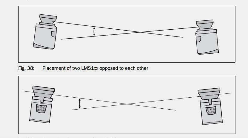
Chart 3-6 mutual interference between lasers
3.4.4.3.2. The Effect of Strong Light
Typically, the ambient light immunity for indoor laser use is approximately 40klux~80klux, and the general indoor light intensity is lower than this value, so indoor lighting does not affect the laser, but direct sunlight should be avoided as much as possible.
3.4.4.3.3. The influence of environmental changes on laserSLAM
The principle of laser SLAM is to construct a point cloud map of the environment by scanning the outline of the environment with a laser radar, and then perform positioning and navigation by matching the constructed point cloud map with the real-time point cloud scanned by the laser. Therefore, if the environmental outline changes significantly after the map is constructed (>30%), the robot may not achieve the expected high precision. If the environmental outline changes even more greatly (>60%), the robot may deviate from the path or even lose its positioning. Therefore, for scenarios where the environment frequently undergoes significant changes and laser SLAM is used, please consider adding auxiliary measures, such as enabling online SLAM or deploying reflective plates or QR codes.
3.5. Battery system
3.5.1. Battery basic performance parameters
Table 3-2 Battery System
Parameter type |
Specific parameters |
Battery type |
Lithium iron phosphate |
Nominal voltage |
48V |
Rated capacity |
30AH |
Standard charging current |
15A |
Charge cutoff voltage |
54V |
Maximum allowable continuous charging current |
≤30A |
Standard discharge current |
15A |
Discharge cut-off voltage |
37.5V |
Maximum allowable continuous discharge current |
≤30A |
Instantaneous maximum discharge current |
≤66A@6S |
Charging temperature |
0℃〜55℃ |
Discharge temperature |
-20℃〜60℃ |
Storage temperature |
-40℃〜40℃(≤3 months) |
Storage temperature |
10℃〜35℃(3 months to 1 years) |
Box dimensions(mm) |
About 255*200*150mm |
IPProtection level |
IP54 |
Cycle life |
≥1500 times @80%SOC5 |
Weight(Kg) |
about12.5KG |
3.6. Sound and light system
3.6.1. Ambient light
Robot indicates the current running status through the color and shape changes of ambient light.
Table 3-3 ambient light
ambient light display |
status |
red |
Emergency stop status |
green |
Running Status |
blue |
In the three-color light of the current prototype, the blue light is not enabled for now, and can be added later based on actual on-site requirements. |
3.6.2. Buzzer
AMR Configure the buzzer for alarm prompts, and the buzzer operates under the following conditions:
When the robot reports errors at the Fatal and Error levels.
3.7. Technical parameters
Table 3-4 Technical Parameters
Parameter type |
Specific parameters |
Model Parameters |
FR-AMR-300 |
payload |
300KG |
Rotation diameter |
990mm |
Positioning accuracy |
±15mm,±1° |
Maximum running speed |
2m/s |
Drive Mode |
Two-wheel differential |
Navigation mode |
laser Slam |
Passability |
slope≤5%,steps≤1cm,gap≤1cm |
protection level |
IP20 |
Front and rear laser obstacle avoidance |
quantity2,coverage360° |
Emergency stop button |
Quantity 2, each opposite corner 1 |
Contact protection |
Piezoelectric edge-touch switch |
Sound and light alarm |
Standard configuration |
Power supply interface |
48V,24V |
Communication Interface |
RJ45 |
Overall dimensions |
800×600×260mm |
Total machine weight |
85KG |
Working Temperature |
0⁓45℃ |
Working humidity |
90%RH |
Equipment Materials |
Steel |
Shell color |
White fine sand texture |
Battery material |
Lithium iron phosphate |
Charging time |
≤2h |
Battery Specifications |
48V,30Ah |
Endurance |
10h |
The road surface is flat, clean, with no obvious undulations. degrees5%=arctan(0.05)≈2.8°. The robot must not stop or turn at slopes, steps, or gaps; it may only pass through them quickly in a direction perpendicular to them.
Positioning accuracy usually refers to the repeatability of the robot navigating to a target site. When the environment scanned by the robot’s LiDAR is relatively stable, the repeatability of the robot navigating to the target site from a fixed direction can reach the expected value. When the robot runs along a virtual path, it will try to follow the path as closely as possible, but repeatability is not guaranteed. That is, the robot can guarantee point accuracy, but not path following accuracy. The robot should not be used as a linear guide.
Basic functions include map editing、upgrade module、log module、navigation module、API interface and so on。
AMR is designed only for indoor transportation, not recommended for outdoor environments.
3.8. Software Functions
3.8.1. Mode switching function
3.8.1.1. Functional Description
The core safety function of the control system operation, used for switching between manual mode and automatic mode.
Manual mode: Allow the operator to directly control the robot’s movement through devices such as a virtual joystick, suitable for debugging and mapping.
automatic mode:The robot executes navigation tasks,navigates according to the planned path,and automatically avoids obstacles。
3.8.1.2. Operation process
Enter mode switch interface
In the top status bar of the main control interface, find the current mode display area
Authentication
The system pops up the password input dialog.
Type the default or administrator-preset password in the input box, click “Confirm” or press Enter to submit.
Execute mode switch
After the password verification passes, the system immediately performs mode switching:
If currently in manual mode, switch to automatic mode.
If currently in automatic mode, then switch to manual mode.
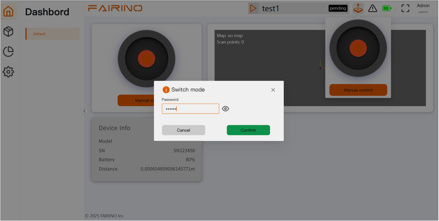
图表 3-7 模式切换
3.8.2. Manual joystick control function
3.8.2.1. Functional Description
This part of the functionality allows users to interact directly with AMR through the software interface,including manual control、environment mapping。
3.8.2.2. Operation process
Ensure the robot is in manual mode and confirm there is enough safe space around it.
Find and look at the virtual joystick component on the interface.
Move the mouse cursor to the center point of the joystick.
Hold the left mouse button, and drag the center point of the joystick according to the expected movement direction:
Drag forward or backward: controls the robot to move forward or backward in a straight line; the greater the drag distance, the faster the robot moves.
Drag left or right: control the robot to move in an arc or rotate in place left or right.
Drag obliquely: combine linear velocity and angular velocity to make the robot move along the corresponding curved path.
When you need to stop the robot,release the left mouse button,the joystick will automatically return to center,the robot will immediately stop moving。
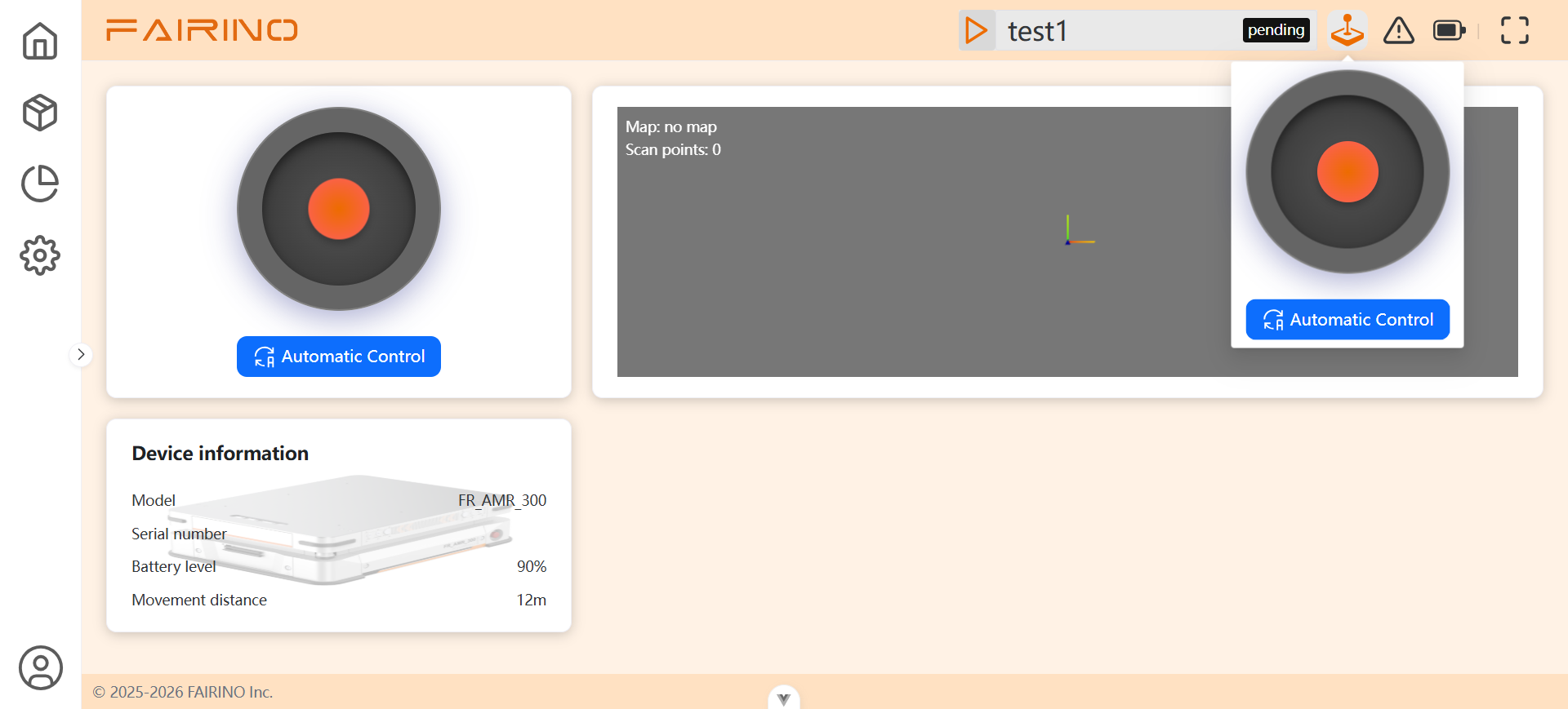
Chart 3-8 joystick control
3.8.3. Mapping Function
3.8.3.1. Functional Description
By manually controlling the robot’s movement, using its onboard LiDAR and odometry data, a 2D grid map of the surrounding environment is constructed in real time.
3.8.3.2. Operation process
Enter map options, create map。
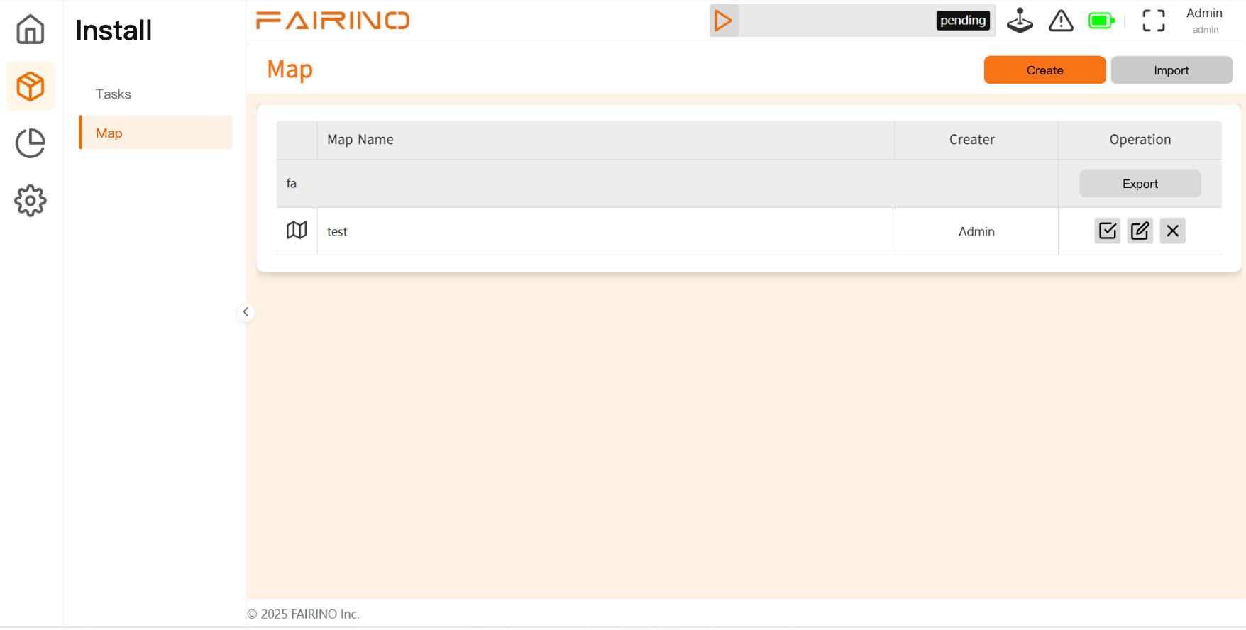
Chart 3-9 Enter Map Options
Enter the map name and station, then click Create.
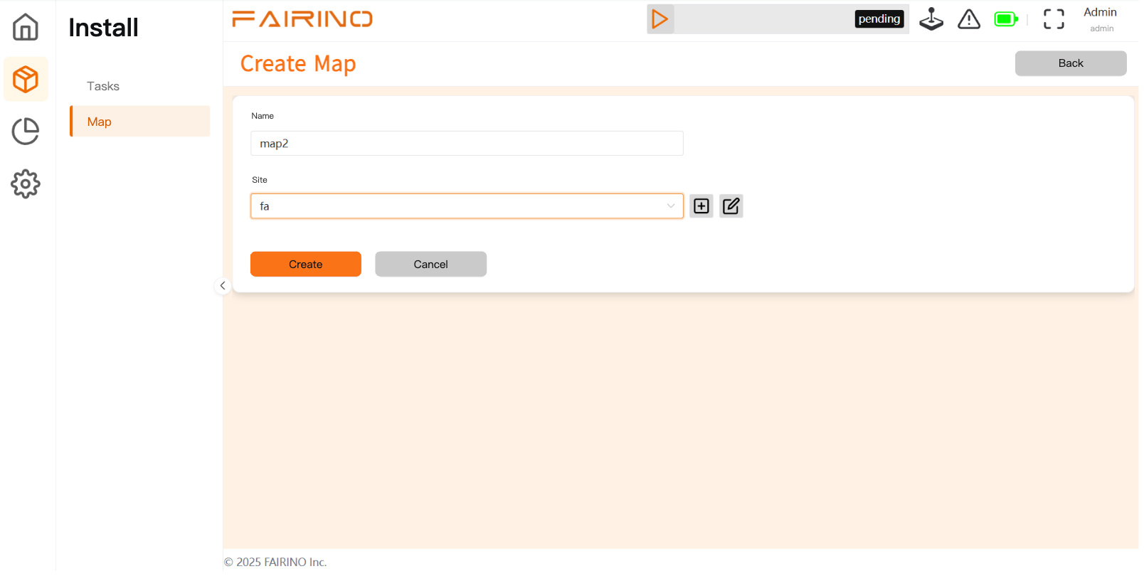
Chart 3-10 Create Map
Use the manual joystick to control and drive the robot to move uniformly and completely within the area to be mapped, ensuring coverage of all passages and corners.
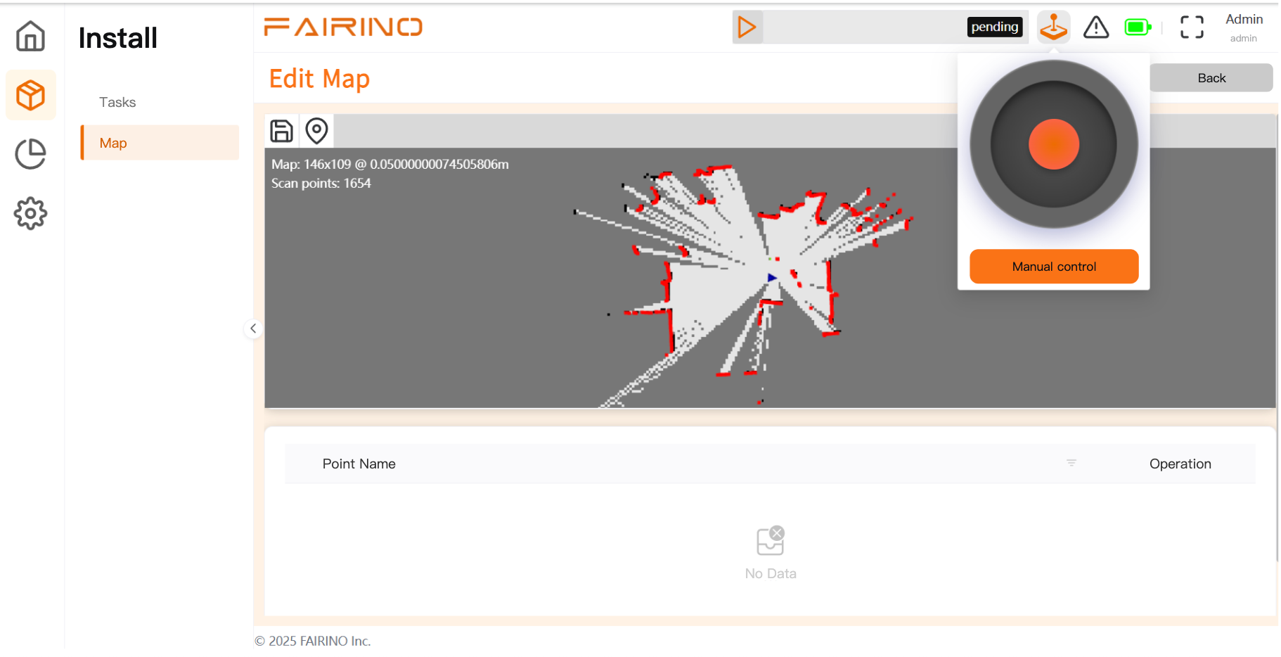
Chart 3-11 Joystick Control
After the mapping is completed or the current map is confirmed to be correct, click the “ Save Map ” button at the top of the interface.
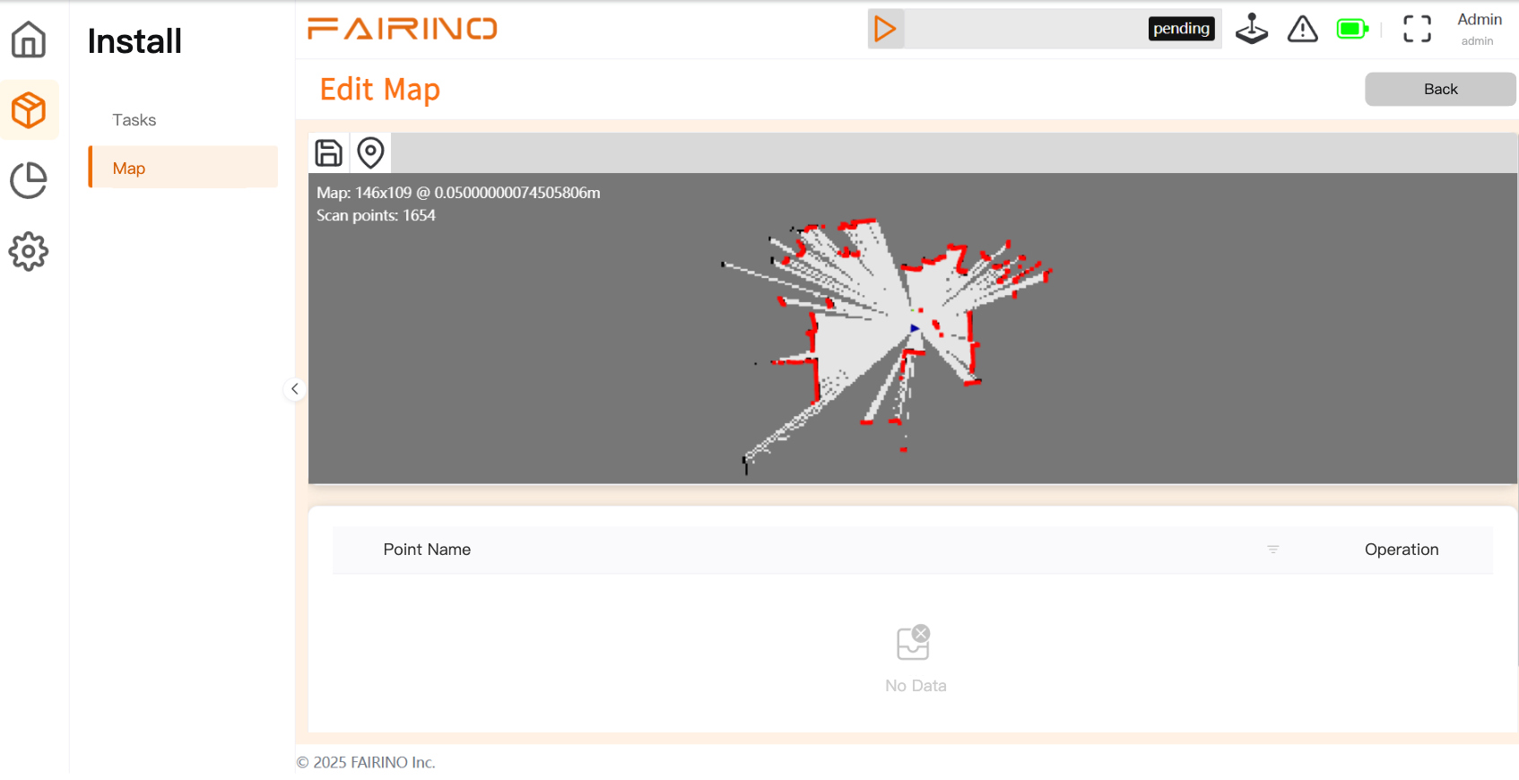
Chart 3-12 Save Map
3.8.4. Load map
3.8.4.1. Functional Description
Retrieve a saved map file from system storage, set it as the currently running map for navigation and mission planning. Click the “ load map ” apply button on the interface.
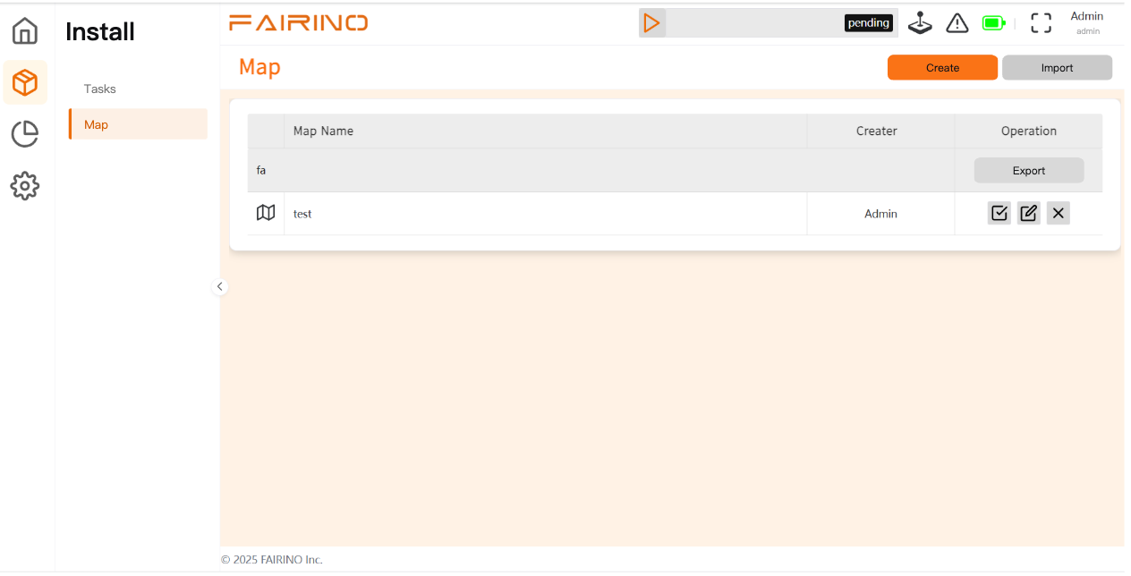
Chart 3-13 Application Map
3.8.5. Record Point
3.8.5.1. Functional Description
Mark and save key positions and poses on the map as target points for robot automation tasks.
3.8.5.2. Operation process
By manual control or move the robot to the target position. Click the compile point button. Add point name.
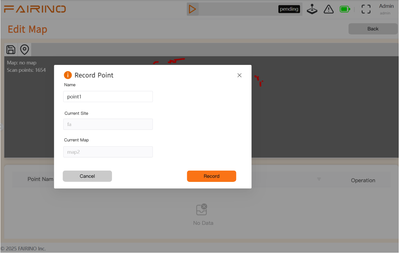
Chart 3-14 records points
3.8.6. Create Task
3.8.6.1. Functional Description
By editing the points moved by AMR, create the tasks it executes.
3.8.6.2. Operation Steps
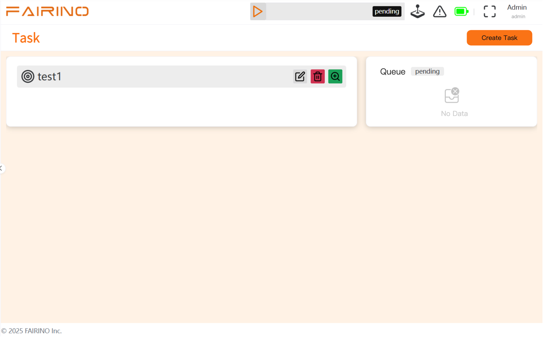
Chart 3-15 enter task options
Enter task name, create task.
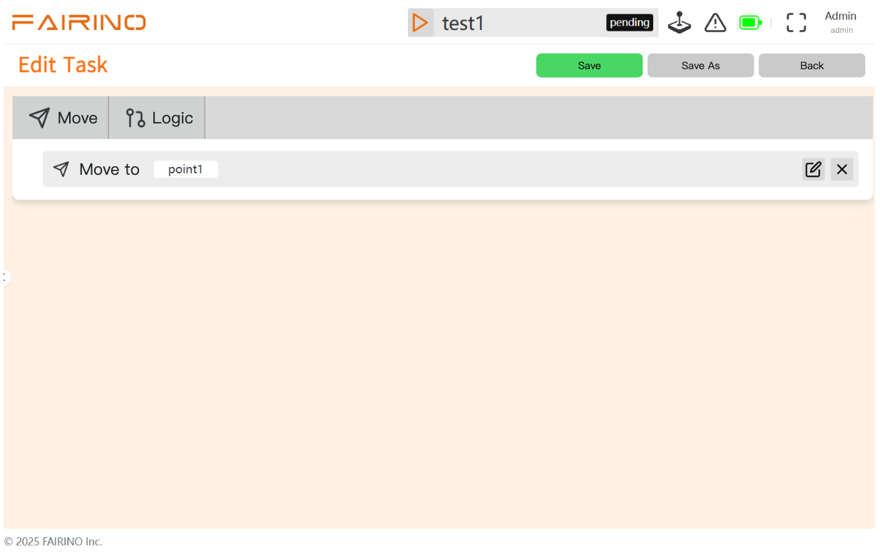
Chart 3-16 Create Task
Click edit task.
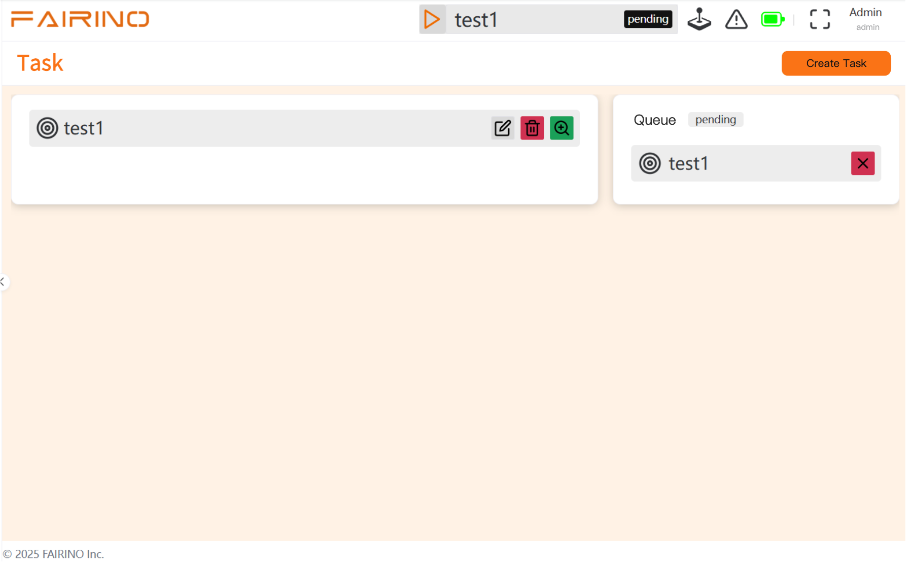
Chart 3-17 Editing Task
Can edit points.
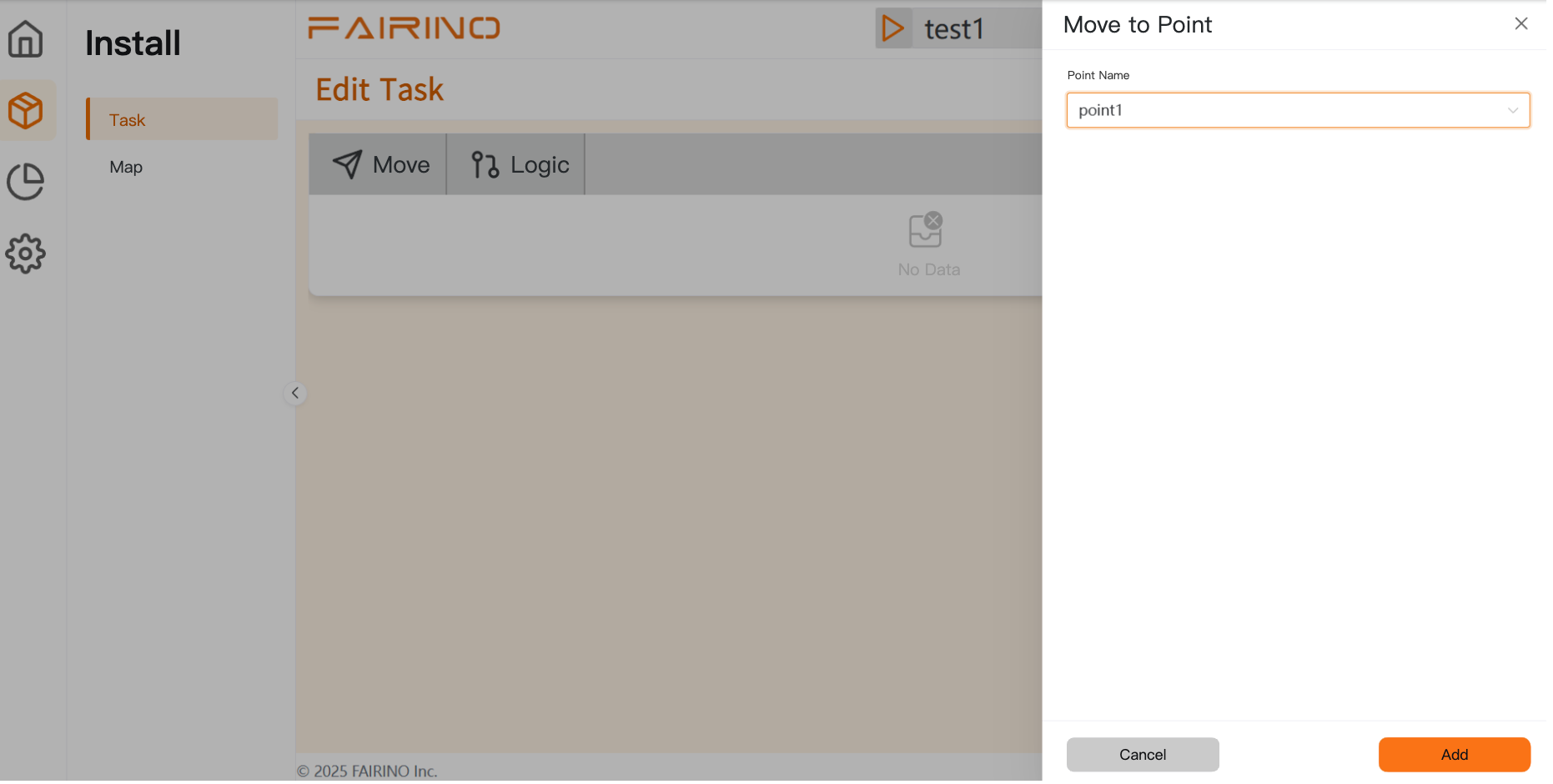
Chart 3-18 edit point
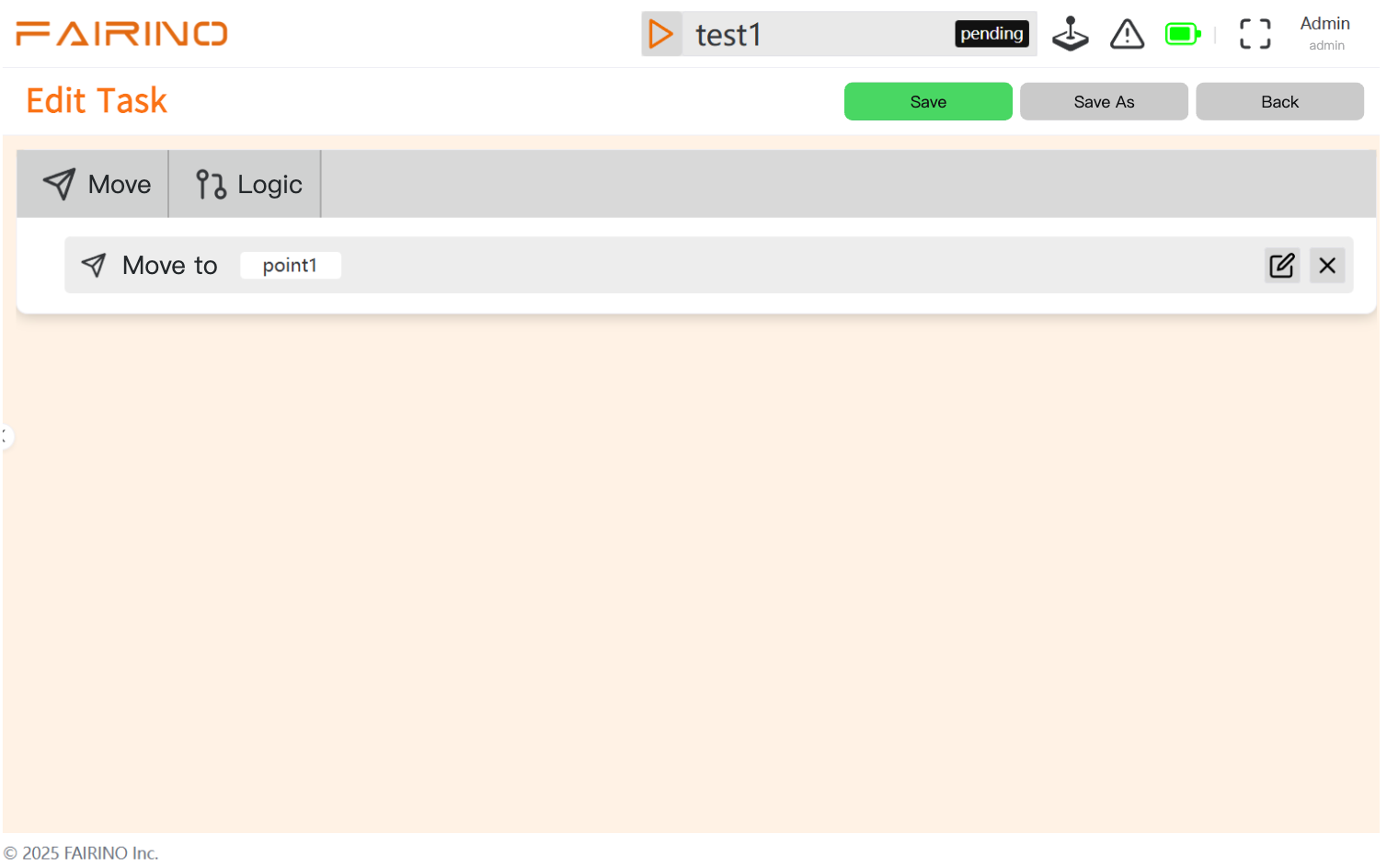
Chart 3-19 Save Task
Finally, save the task.
3.8.7. Run Task
3.8.7.1. Functional Description
Execute an edited and saved task script to make the robot automatically complete a series of tasks defined in the script.
3.8.7.2. Operation process
In the “ script management ” interface, add the Lua script to the task queue。
Click the “ Run Script ” button。Users can view the robot’s task status in real time on the interface。If you need to interrupt the task,click the “ Stop Script ” button。
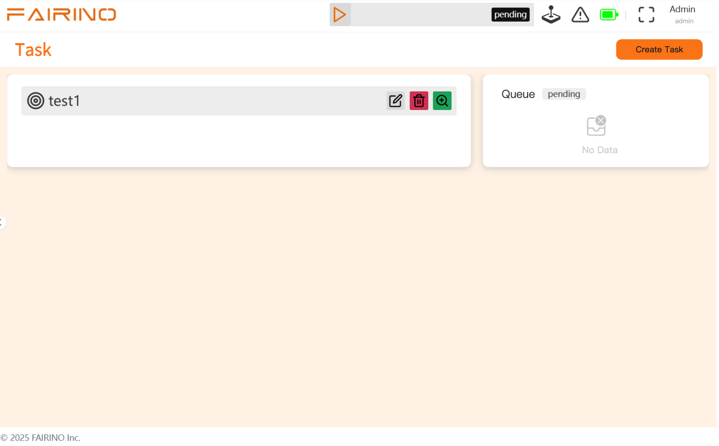
Chart 3-20 Run task
3.8.8. Operation Control and Safety Monitoring
3.8.8.1. General Security Fundamentals
Mode awareness: The safety PLC always knows the current operating mode (manual/automatic).
Independent monitoring: The safety PLC continuously monitors the AMR’s actual motion status via proximity sensors.
3.8.8.2. Manual Mode Process (Joystick Control)
Control path:operator -> joystickHMI -> main controller -> motor driver -> motor。
Safety handshake: The main controller, while controlling the motor, synchronously sends the real-time speed command to safety PLC.
Safety logic:
When the joystick is centered, the main controller sends a zero-speed command.
After safety PLC delays for 0.5 seconds, verify whether the actual speed is zero.
Verification failed (still moving) -> triggers emergency stop. After the emergency stop is triggered, the inputs from the emergency stop button and LiDAR are processed through the safety PLC logic, and the relay cuts off the servo drive power supply, triggering the power-off brake.
3.8.8.3. Automatic Mode Process(Task Control)
The core of this pattern is the legitimacy of task instructions and the predictability of states.
Task startup phase - “secure boot permission”
Instruction issuance: The dispatching system sends task commands to the main controller (e.g., go to point X).
Safety Notice:The main controller must send a clear “ task start ” safety signal to the safety PLC before executing motion。This signal essentially informs the safety PLC:“ subsequently detected motion,is triggered by a legitimate automatic task,please allow。”
SafetyPLCresponse: after receiving the “task start”signal, the safetyPLCclears the alarm for “unintended movement”, and enters the automatic task motion monitoring state.
Task execution phase - “motion process monitoring”
Normal Control: The main controller plans the path, controls the driver, and drives the robot to move toward the target.
Continuous monitoring:Safety PLC at this stage,in addition to monitoring regular safety sensors(emergency stop、anti-collision、zone),will also:
Verify whether the motion command and the mode match.
Monitor faults such as motion overspeed and position deviation.
Mission end phase - “ safety status confirmation ”
Task completed: main controller confirms robot arrived at target, task logic completed.
Safety notice: The main controller must send a “ task completion ” safety signal to the safety PLC. This signal informs the safety PLC: The automatic motion in the “ plan has now ended, and the robot should enter a stationary or standby state. ”
Safety PLC logic switching: After receiving the “ task completion ” signal, Safety PLC updates the expected state to “ stationary ”. At this point, if any non-command motion is detected again, strict monitoring will be resumed.
3.8.8.4. Critical Safety Fault Logic (Automatic Mode)
Fault scenario: The safety PLC does not receive the “Task Start” signal.
Safety response: In this state,the default expectation of safety PLC is that “ should not have automatic motion ”。
If at this time safety PLC detects that AMR is moving, then it immediately determines that it is “ unauthorized abnormal movement ” or “ command loss fault ”。 Safety PLC will immediately trigger a protective stop, and report the corresponding fault code.
3.8.9. Maintenance
3.8.9.1. Diagnostic function
3.8.9.1.1. Functional Description
Through the maintenance entry in the system settings, the connection status of each hardware device can be monitored in real time. When a cable connection error or omission occurs, the system will display an abnormal alarm and provide a specific error description in the diagnostic information, making it easy to quickly locate the problem (see the diagnostic interface in Figure 3.6-1 ).
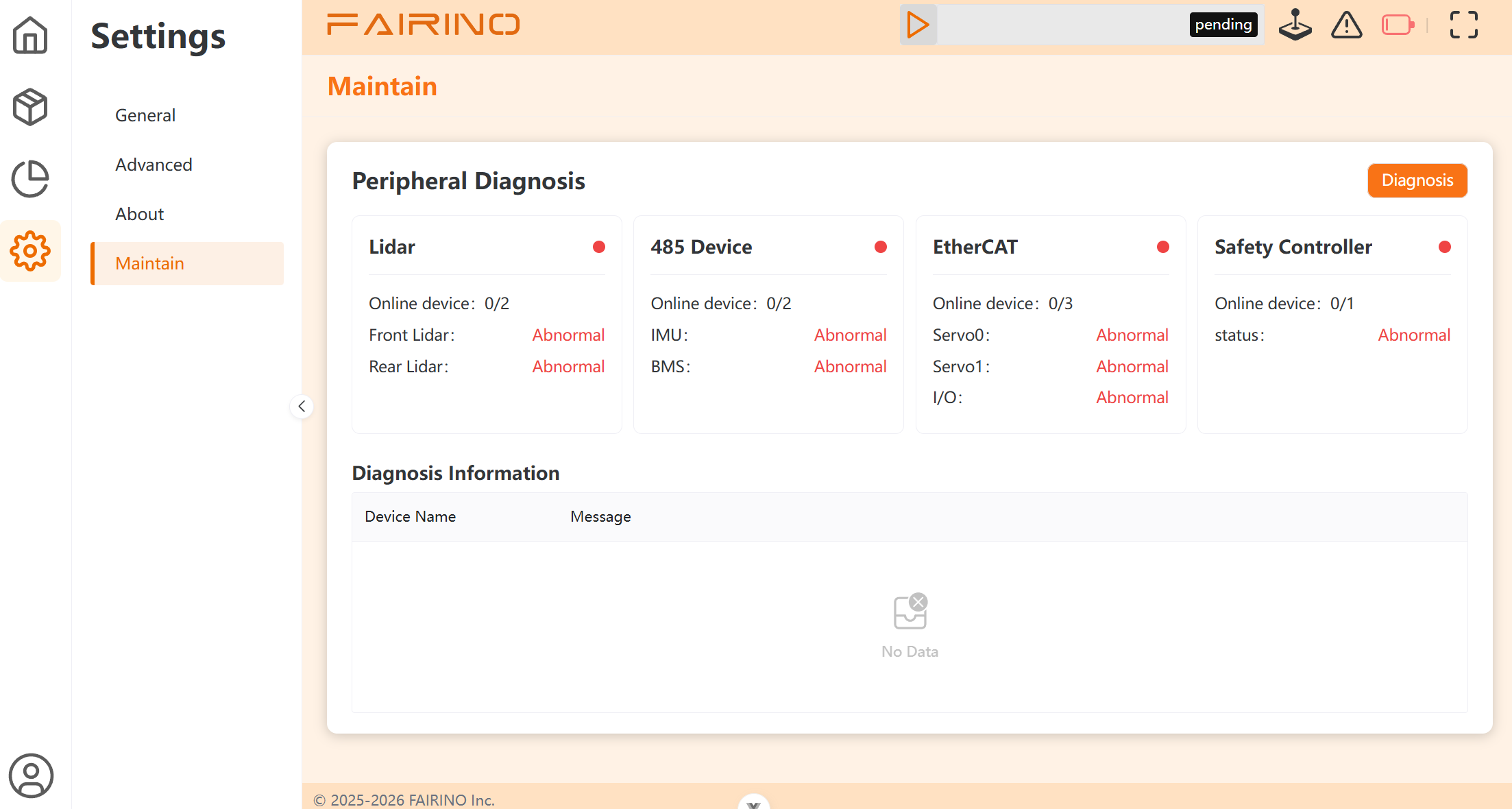
Chart 3-21 diagnostic interface
3.8.9.1.2. Operation process
Click the “One-Click Diagnosis” button in the upper right corner of the interface.
Check the status feedback of each device.
Troubleshoot based on the possible error messages listed below.
3-5 Diagnostic Error Information Table
Front Radar Status |
WARN: no scan >2s: The most recently received topic was 2 seconds ago, the radar may have been briefly offline
FAIL: no scan >20s:the most recently received topic was 20 seconds ago
|
FAIL:never received data: The device was disconnected before power-on. |
Rear radar status |
WARN: no scan >2s: The most recently received topic was 2 seconds ago, the radar may have been briefly offline
FAIL: no scan >20s:the most recently received topic was 20 seconds ago
|
FAIL:never received data: The device was disconnected before power-on. |
IMUstatus |
FAIL: RS485 disconnected (zero data):Disconnect after establishing the connection |
FAIL:never received data: The device was disconnected before power-on. |
BMSStatus |
FAIL: RS485 disconnected (zero data):Disconnect after establishing the connection |
FAIL:never received data: The device was disconnected before power-on. |
safety controller |
WARN: no data >2s: the most recently received topic was 2 seconds ago
FAIL: no data >20s: latest received topic 20 seconds ago
FAIL: Modbus comm fault (…): disconnects after establishing connection
|
FAIL:never received data: The device was disconnected before power-on. |
Servo0status |
FAIL: slave state is SAFEOP (expected OP):
FAIL: slave state is PREOP (expected OP): Slave station starting up
FAIL: slave state is INIT (expected OP):Slave initialization
FAIL: cannot execute ethercat CLI (popen): has not configured passwordless execution permission for the ethercat command
FAIL: slave not found on bus:Disconnect after connection established
|
FAIL: ethercat CLI error (master not running or no slaves):The device has been disconnected before power-on. |
Servo1Status |
FAIL: slave state is SAFEOP (expected OP):
FAIL: slave state is PREOP (expected OP): Slave station starting up
FAIL: slave state is INIT (expected OP):Slave initialization
FAIL: cannot execute ethercat CLI (popen): has not configured passwordless execution permission for the ethercat command
FAIL: slave not found on bus:Disconnect after connection established
|
FAIL: ethercat CLI error (master not running or no slaves):The device has been disconnected before power-on. |
IOStatus |
FAIL: slave state is SAFEOP (expected OP):
FAIL: slave state is PREOP (expected OP): Slave station starting up
FAIL: slave state is INIT (expected OP):Slave initialization
FAIL: cannot execute ethercat CLI (popen): has not configured passwordless execution permission for the ethercat command
FAIL: slave not found on bus:Disconnect after connection established
|
FAIL: ethercat CLI error (master not running or no slaves):The device has been disconnected before power-on. |
3.8.10. Log Export Function
3.8.10.1. Functional Description
Output various types of log data generated during system operation (such as robot status, task records, error alerts, operation history, etc.) in file form, for offline analysis, troubleshooting, data auditing, or system backup.
Select log settings, system log, click the download button to download the log.
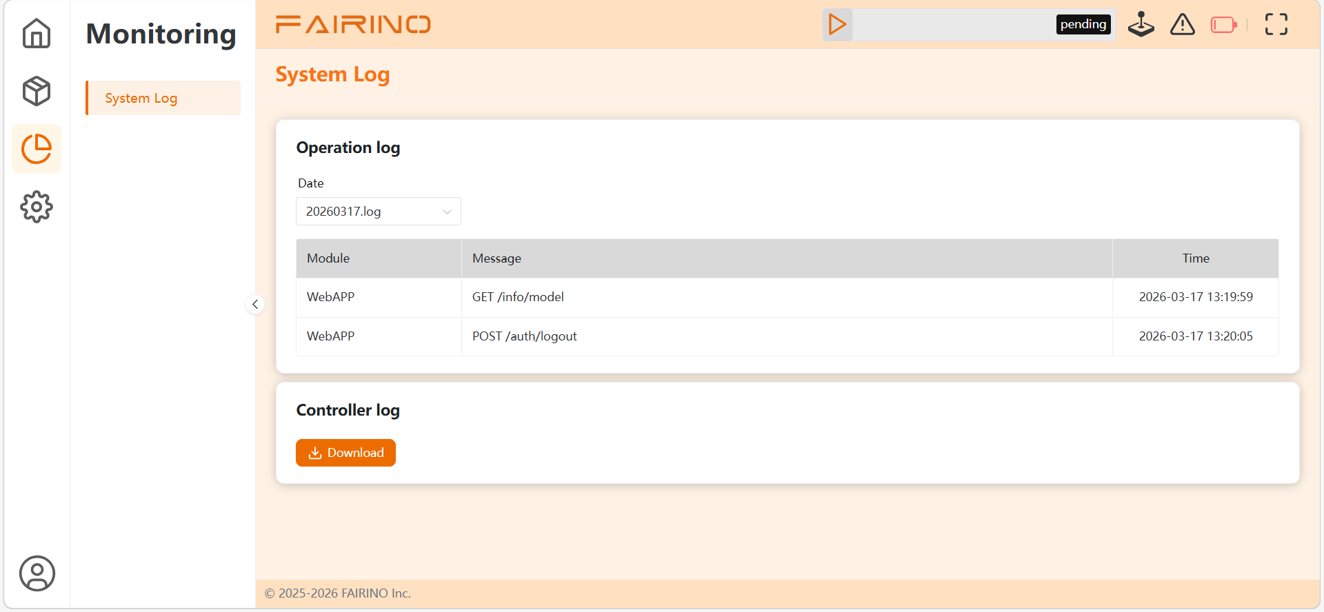
Chart 3-21 Download Log
3.8.11. Parameter Configuration
3.8.11.1. Functional Description
Through the system and advanced settings interface, adjust and optimize the robot’s core motion performance and the costmap parameters required for navigation and obstacle avoidance, to adapt to different operating environments and performance requirements.
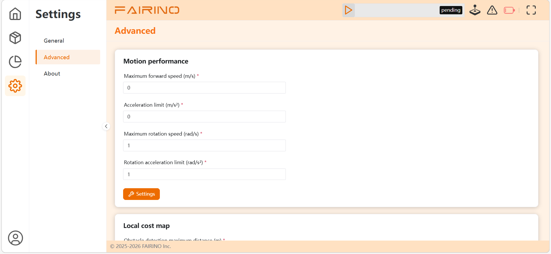
Chart 3-22 Parameter Configuration
3.8.12. Upgrade functionality
3.8.12.1. Functional Description
Through the software upgrade entry in system settings, detect and install the new version of robot control system software, to obtain new features, performance optimizations, or fix known issues.
3.8.12.2. Operation process
Confirm the upgrade file: Obtain the correct upgrade software package from the device supplier or administrator, and confirm that its version number is higher than the current version and applicable to the current robot model.
Ensure the environment is safe: Move the robot to an open, stable area, and ensure that the robot will not execute any tasks during the upgrade process, and that no personnel or obstacles are nearby to interfere. Keep the power connection stable.
In the software main interface, enter “ settings ”, find and click the “ upgrade ” option.
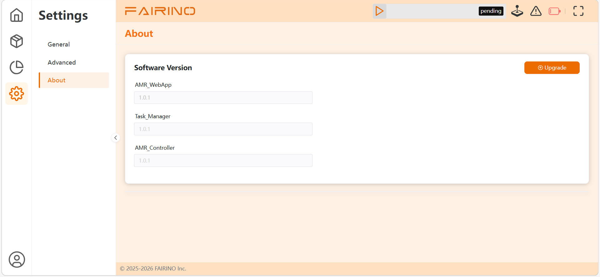
Chart 3-23 Upgrade Interface
Select upgrade file。
After confirming it is correct,click “ to start upgrade ” or “ upgrade ” button。Execute the upgrade operation,wait for the upgrade to complete,the time is approximately 20s。During the entire upgrade process,do not close the software、disconnect the robot power or perform any other operations,otherwise it may cause system damage。After the upgrade is completed,you will be prompted “ upgrade successful ”。
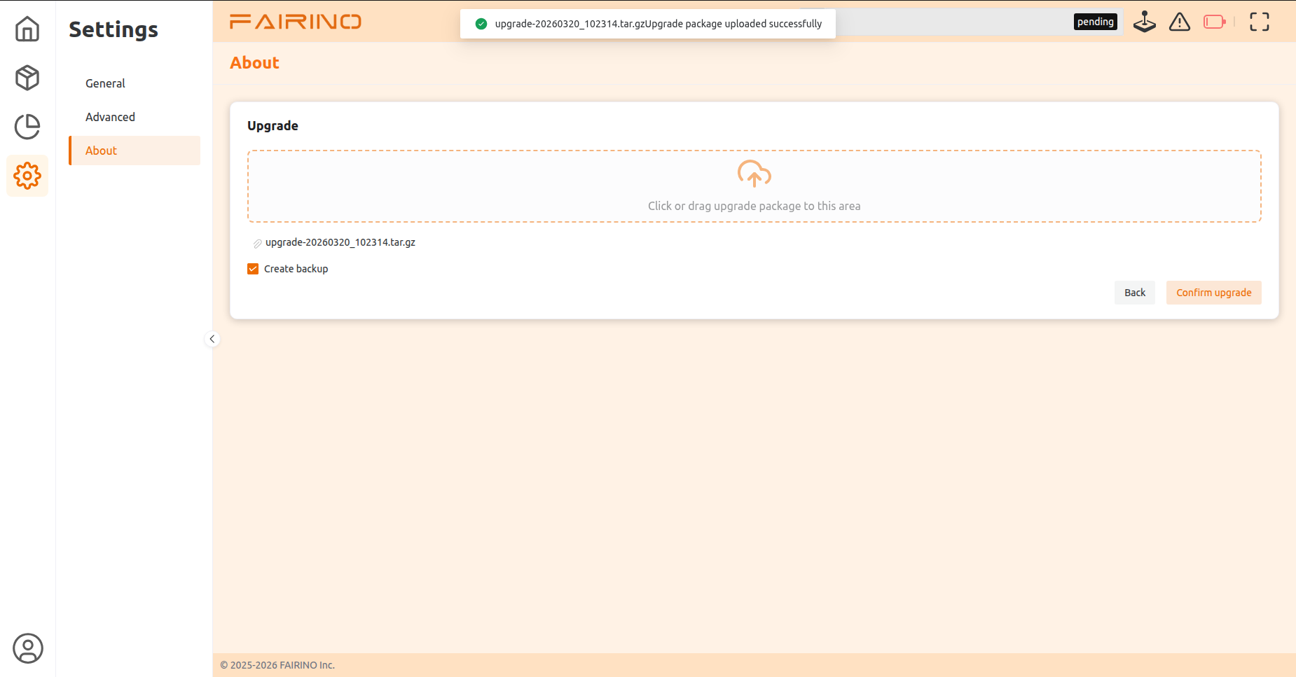
Chart 3-24 Confirm Upgrade
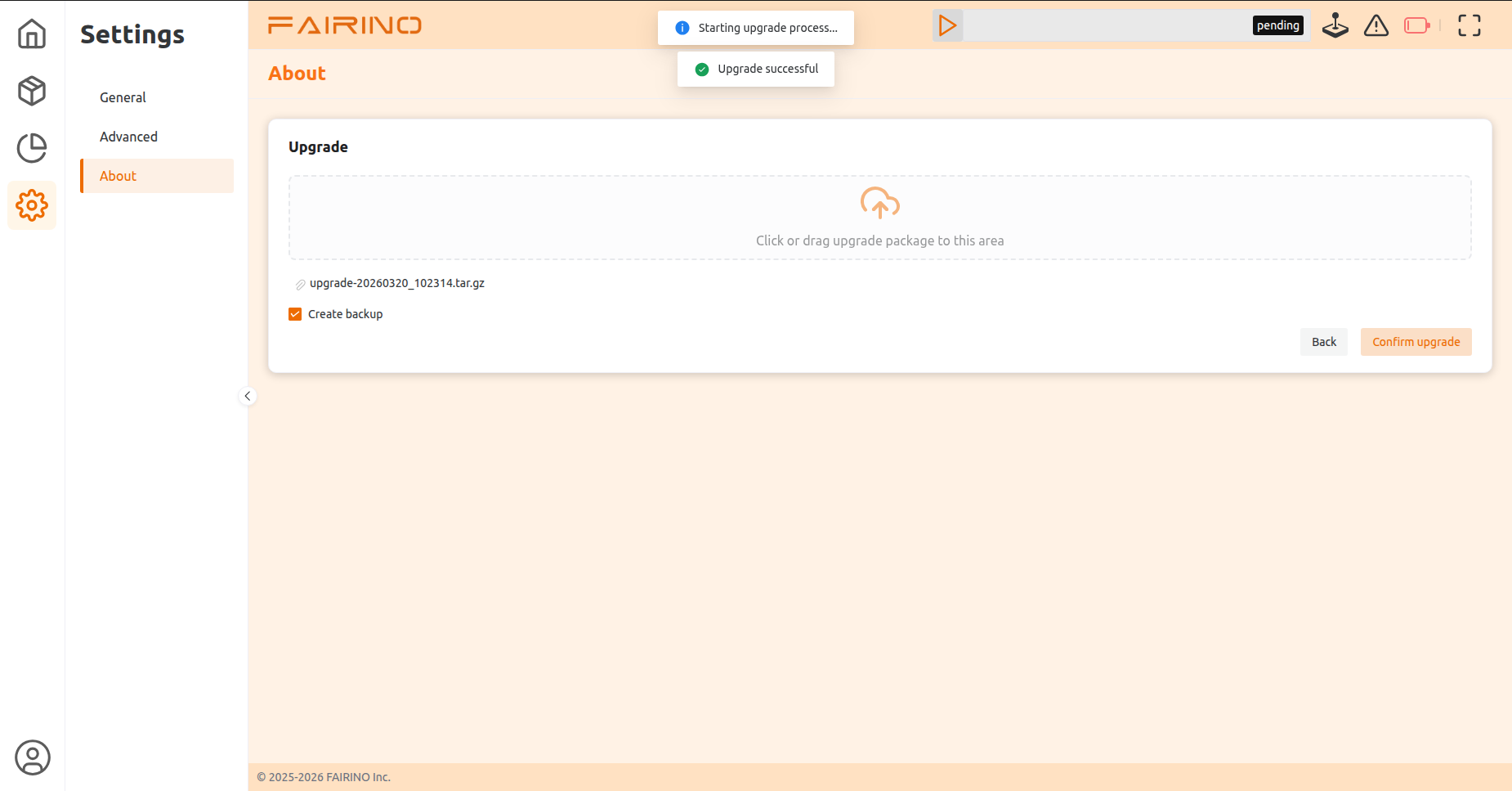
Chart 3-25 upgrade successful
Manually restart the robot. After restart, log in to the software again, enter the “Settings” -> “Software Update” page again, and confirm that the software version number has been updated to the target version.
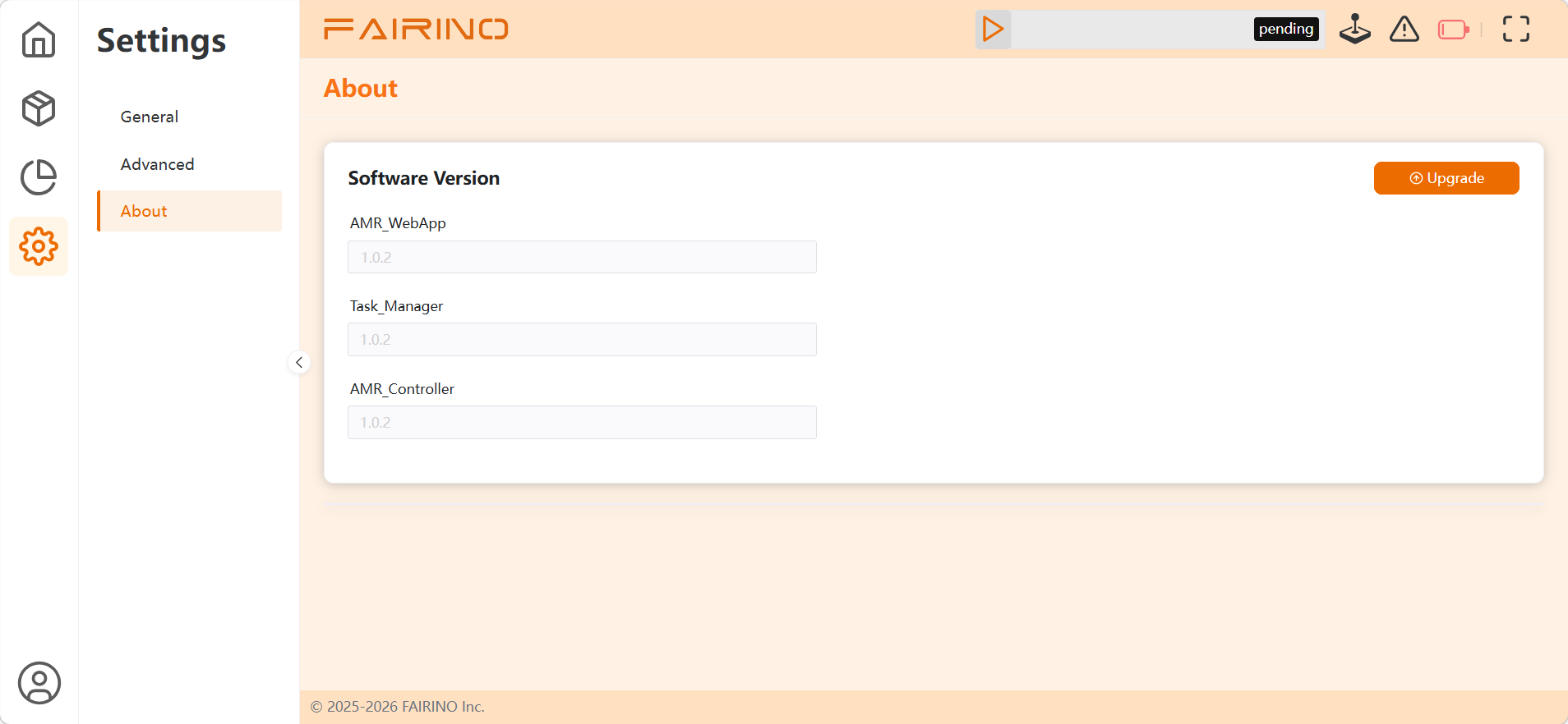
Chart 3-26 upgrade successful version number
3.9. Network Requirements and Configuration
wireless network protocol:IEEE 802.11 a/b/g/n client
Broadband speed value: ≥100Mbits
signal strength requirement:≥-60dBm
Network latency requirement:Average latency time≤100ms
3.10. Security Feature List
LiDAR active obstacle avoidance
Real-time scanning of path obstacles, triggering deceleration or stopping when there are obstacles in the radar protection area.
Low battery protection
When the battery level falls below the safety threshold(20%),a low battery alarm is triggered,and the buzzer sounds。
Emergency stop button
Emergency stop buttons are located at two diagonal points on the fuselage; pressing them instantly cuts off all power.
Sound and light alarm
Trigger different ambient light colors during operation and emergency stop states; trigger the buzzer when emergency stop occurs or when the battery level falls below the safety threshold.
Power On/Off Protection
Only through the key can control the power on/off of AMR.